Safety – The Comprehensive View
The influence of vehicle dynamics on the functional safety of ADAS/AD.
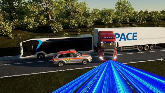
The integration of ADAS/AD functions in vehicles serves one goal: To ensure and, where possible, increase the safety of all road users. But what needs to be considered in the validation of intelligent systems? Is the consideration of regulations, test scenarios, sensors, and functions sufficient, or does the dynamic behavior of the vehicle also play a decisive role?
Vehicle Dynamics
A driving dynamics insight: Physically, vehicles are more than a point mass and their dynamic driving behavior has a particular influence on critical driving situations. A simple example might be braking on surfaces with different friction coefficients: The vehicle starts skidding as torque is generated around its vertical axis. Even if stability systems intervene to prevent rotation, safety aspects must always be evaluated from a sensor perspective. But what information do these provide when dynamic driving effects influence the imaging sensor technology? And how do functions for ADAS/AD (advanced driver assistance systems/autonomous driving) use this information?
Testing via Simulation
Fortunately, we do not have to perform any elaborate and dangerous maneuvers on the proving grounds to investigate the vehicle’s dynamic behavior. With just a few clicks, simulations deliver revealing insights. We want to look at selected relevant situations using the dSPACE tool suite Automotive Simulation Models (ASM) in combination with the sensor-realistic simulation software AURELION.
1) Vehicle Dynamics Testing: Emergency Braking at the Limit
A truck is used to perform emergency braking at the limit on roads with different friction coefficients, for example, due to leaves, wetness, or snow, and with the electronic brake system (EBS) switched off, in order to separately highlight the influence of the vehicle dynamics on the overall system behavior. The braking process is triggered in each case by the automatic emergency braking (AEB) system as part of an ADAS on the basis of the detected collision risk.
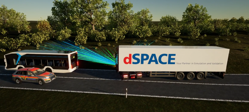

The examples show that emergency braking can be realistically represented in the simulation only if all physical aspects of driving are taken into account (friction values, torques between the truck and trailer). And the function of the ADAS can only be fully evaluated and validated when the effects of vehicle dynamics are considered. The stability of the overall system must not be disregarded, especially when deciding on emergency braking at the limits of vehicle dynamics.
Taking into Account the Overall Network
In addition, the ASM vehicle models also take into account the behavior of the braking system, both hydraulic and pneumatic, and therefore offer the possibility of testing an ADAS/AD ECU in conjunction with other ECUs, for example, the interaction with an electronic stability controller (ESC). The benefit: The performance of the entire system is included in the evaluation, and the validation is not only provided for a single component, but for an entire system. This provides the ADAS/AD developer with expanded and more sophisticated options for understanding the behavior of the entire system at an early stage and adjusting it if necessary.
2) Vehicle Dynamics Testing: Pitch Angle of the Driver Cabin During Braking
When a truck brakes, the accelerations in the direction of travel cause the driver cabin to pitch toward the chassis due to the degree of freedom. The camera sensors installed in the driver cabin therefore change their angle of view. The installed ADAS/AD control units compensate for this change in view so that the distance to the detected obstacle is calculated correctly.
In order to also include pitch angle compensation in the simulation and to calibrate the ECUs correctly, the pitch angle must correspond to the physical conditions. This is essential for both object detection by individual sensors and downstream sensor fusion. For example, a camera sensor installed in the cabin must achieve the same result in obstacle detection as the radar sensor installed at the bottom of the chassis. Otherwise, there is a risk that the entire system could fail, with potentially serious consequences.
Depending on the driving situation, an originally detected obstacle can disappear partially or even completely from the sensor’s field of view (FoV), especially in the case of very strong braking decelerations and a resulting high pitch angle. The behavior of the ADAS/AD functions in these particularly critical situations must be known and validated.
The following figures show how this behavior can be clearly displayed with ASM Truck and correctly integrated into the simulation with regard to the physical characteristics. The physics-based sensor models in AURELION let you freely configure the sensor position, in particular an installation position of the camera sensor in the cabin with additional degrees of freedom:

3) Vehicle Dynamics Testing: Ruts in the Road Surface
One important function of ADAS/AD control units for trucks is active lane keeping assistants (LKA). They must not only detect the road correctly, but also be robust against external disturbances. Such a disturbance can occur, for example, due to the tire-road contact points when the vehicle is in a rut, or lane groove, and has to counter steer.
For reliable validation of the LKA system, it is therefore necessary to be able to realistically represent such disturbance variables in a closed-loop simulation.
With the ASM Road simulation model, any road surface can be simulated and flexibly parameterized. This gives you very broad test coverage with reproducible tests that you can no longer achieve in real test drives.

4) Vehicle Dynamics Testing: Consideration of Crosswind
Another aspect that is particularly important for trucks is the consideration of crosswinds in automated lane keeping. In connection with wind sheltering, high lateral gusts are generated, which can lead to directional changes and instabilities in vehicles with trailers and semi-trailers. The ADAS/AD control unit must recognize these and respond appropriately.
Again, ASM simulation lets you replicate such situations with high variability. This lets you ensure a high level of maturity of the algorithms at an early stage. Last but not least, these tests are essential for validating the control units.

Evaluation and Overall View
By including the highly accurate vehicle dynamic system behavior, it is possible to simulate the influence of physical effects on ADAS/AD systems and to use them productively for validation. In this way, vehicle dynamics simulation makes an essential contribution to reliable development and validation and ensures robust ADAS/AD ECUs.
In the event of fatal consequences during critical driving situations, the interaction of different effects is often decisive. Precisely these combinations, which often cannot be represented in reality, are made possible by the simulation. The use of realistic traffic and vehicle dynamics simulation is the foundation for an efficient approach to the development of ADAS/AD systems. In addition to development efficiency, both test depth and test breadth increase, which in turn improves the quality of the individual functions and therefore the interaction in the network.
Author:

Michael Peperhowe
Lead Product Manager
dSPACE
Disclaimer:
All simulations shown were performed with the dSPACE multi-physics tool suite ASM (Automotive Simulation Models). The sensor simulations and animations were calculated and rendered using the high-fidelity 3-D software AURELION.
Published in Telematics Wire

